

Operation side support roller bearing seat of hot rolling mill
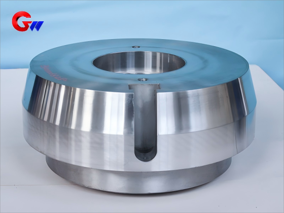
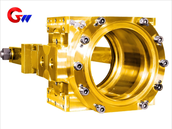
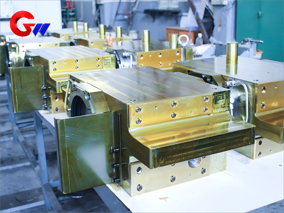
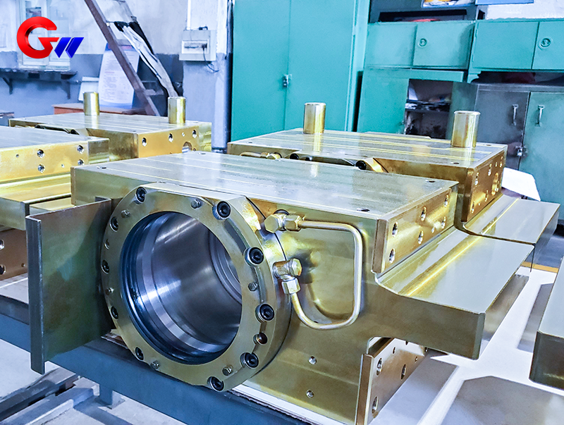
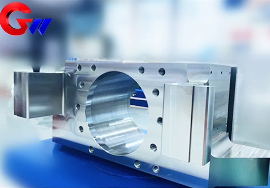
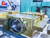
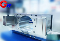
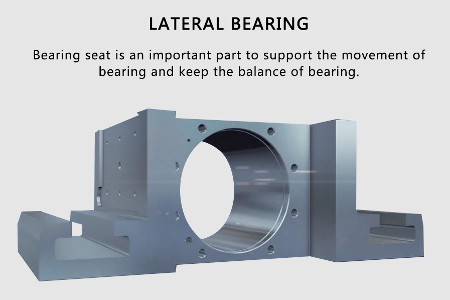
The operation-side support roller bearing seat is a structural support component designed for the support roll assembly of a hot rolling mill. It provides stable bearing support, accurate roll positioning, and reliable mounting interfaces for continuous rolling operations.
The component can be manufactured from cast steel or forged alloy steel according to the load, rolling speed, impact conditions, and service requirements of different mill configurations. Precision machining and coordinate measurement are applied to critical bearing holes, mounting surfaces, positioning features, and other functional interfaces.
Key Features
- Precision bearing-hole control: Diameter tolerance to H7 / IT7, with roundness and cylindricity controlled to ≤0.02 mm.
- Controlled surface finish: Bearing-hole surface roughness Ra ≤1.6 μm, with bearing mating surfaces requiring Ra ≤0.8 μm.
- Accurate installation: Mounting-surface flatness controlled to ≤0.05 mm/m, with bolt-hole position tolerance of ±0.1 mm.
- Heavy-duty material options: Available in ZG270-500, ZG35CrMo, 42CrMo, and 35CrNiMo according to operating requirements.
- Flexible bearing configuration: Compatible with four-row tapered roller bearings and oil-film bearing systems such as MORGOIL.
Brand: GW Precision
Product Origin: Luoyang, China
Delivery Time: According to contractual agreement
Supply Capacity: Available according to production requirements
- GW Precision
- China,Luoyang
- Contractual Stipulation
- Anual Capacity is 1000 pieces
- Information
Operation side support roller bearing seat of hot rolling mill
Material and Manufacturing Standards
The operation-side support roller bearing seat is a structural support component designed for the support roll assembly of a hot rolling mill. Its primary functions include supporting the bearing arrangement, maintaining the required alignment of the support roll, providing stable mounting interfaces, and transferring rolling loads between the roll system and the mill housing.
The bearing seat is manufactured according to defined material, mechanical-property, machining, dimensional-tolerance, and inspection requirements. Material and process configurations can be adapted to different operating conditions, including conventional rolling, high-load production, and high-speed rolling applications.
Main Material
Cast steel options include ZG270-500 in accordance with GB/T 11352 and ZG35CrMo for higher-strength operating conditions.
Forged steel options include 42CrMo according to ASTM A29 and 35CrNiMo for heavy-duty, high-speed rolling mill applications.
The selected material depends on structural loading, operating speed, impact conditions, dimensional requirements, and service environment. Cast steel provides a practical combination of strength, castability, and structural integrity for large support components, while alloy forged steel can be selected where higher strength and fatigue resistance are required.
Chemical Composition of 42CrMo
As a representative forged-steel grade, 42CrMo has the following specified chemical composition:
| Element | C | Si | Mn | Cr | Mo | P | S |
|---|---|---|---|---|---|---|---|
| Range | 0.38–0.45 | 0.17–0.37 | 0.50–0.80 | 0.90–1.20 | 0.15–0.25 | ≤0.025 | ≤0.025 |
The material specification is intended to provide a suitable balance of strength, toughness, machinability, and dimensional stability. For a support roller bearing seat, these properties are important because the component operates around the bearing and must remain structurally stable under repeated rolling loads.
Product Material Options
| Application | Typical Material |
|---|---|
| Working roll forgings | 45 steel, 40Cr, 42CrMo |
| Support roll castings | ZG310-570, ZG270-500 |
The material configuration is selected according to the roll type and associated bearing-support requirements. A support roll assembly requires a rigid and accurately machined bearing seat to maintain bearing positioning and roll alignment during operation.
Mechanical Properties
For 42CrMo in the quenched and tempered condition, the specified mechanical properties are:
| Property | Required Value | Test Standard |
|---|---|---|
| Tensile strength (Rm) | ≥900 MPa | GB/T 228.1 |
| Yield strength (Rp0.2) | ≥750 MPa | GB/T 228.1 |
| Elongation (A) | ≥14% | GB/T 228.1 |
| Impact energy at room temperature | ≥40 J | GB/T 229 |
| Hardness | 260–320 HBW | GB/T 231.1 |
These mechanical properties provide a reference for material acceptance and process control. In a hot rolling mill operating under high rolling forces, sufficient tensile and yield strength help the bearing seat maintain structural integrity.
Adequate elongation and impact toughness also contribute to resistance against shock loading and service-related stress. The final material grade and heat-treatment condition can be selected according to the actual design and operating requirements of the mill.
Precision Machining Process
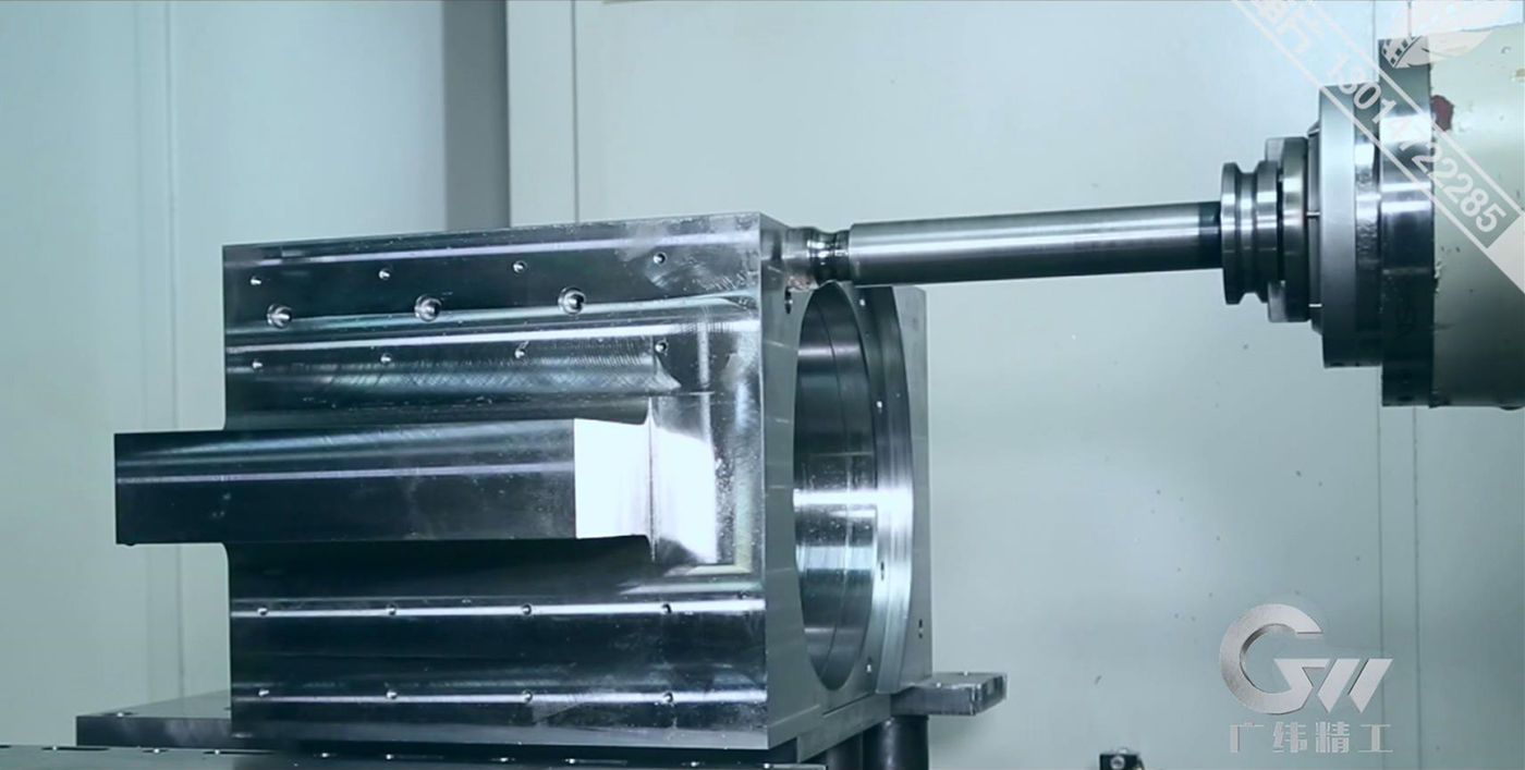
GW Precision has developed a controlled machining process for the manufacture of the operation-side support roller bearing seat through long-term production experience.
The manufacturing sequence uses multiple machining stages to establish reliable reference surfaces, produce functional holes, maintain dimensional relationships, and complete final inspection.
1. Vertical Machining Center
Initial milling is performed according to the engineering drawing. A reference belt is established with a milling depth of approximately 5 mm, while approximately 1.5–2 mm of machining allowance is retained on each relevant side.
After the initial operation, the component is cleaned and sharp burrs are removed before first-piece inspection.
2. Horizontal Boring Machine
Major surfaces, grooves, and holes are processed while the specified machining allowance is retained.
Approximately 1.5–2 mm is reserved on relevant surfaces, 1.5–2 mm for designated grooves, 3–4 mm for specified hole allowances, and 2–3 mm for relevant hole lengths.
Burrs and sharp edges are removed before inspection.
3. Vertical Machining Center
Finish milling is performed according to the requirements for non-tolerance fitting surfaces. The reference edge is established at the specified depth, and boring operations continue according to the engineering drawing.
The remaining machining allowance is controlled to approximately 1.5 mm where specified. Center holes are established at the ends of relevant holes to support subsequent machining and dimensional control.
4. Horizontal Machining Center
The workpiece is mounted and aligned using the designated center hole and reference edge. Functional surfaces are machined according to the drawing.
Center holes are established on the end faces of relevant holes, while deep-hole processing is completed according to the required dimensions. Dimensional and geometrical tolerances are controlled throughout the operation.
5. Vertical Machining Center
Existing holes are used as machining references for precision boring. Hole processing is completed according to the specified dimensions, followed by rolling of the hole surface where required.
A controlled allowance is retained before final sizing. Finished holes are checked for dimensional accuracy, and the component is cleaned and deburred before inspection.
6. Bench Work
Thread-bottom holes and positioning holes are completed according to the engineering requirements.
7. Bench Work
Additional oil holes and screw holes are drilled and tapped. The component is cleaned and sharp burrs are removed before first-piece inspection.
8. Final Inspection
The completed bearing seat is cleaned, deburred, inspected, and released with an inspection record according to the applicable quality requirements.
This multi-stage machining process helps control the dimensional relationship between bearing holes, mounting surfaces, positioning features, and other functional interfaces. Such control is important because deviation at one interface can influence bearing installation and the alignment of the support roll.
Structural Design and Tolerance
The bearing hole is one of the most important functional features of the operation-side support roller bearing seat.
The specified bearing-hole accuracy includes a H7 diameter tolerance, corresponding to IT7 grade control. Roundness and cylindricity are controlled to ≤0.02 mm.
The surface roughness of the bearing hole is specified at Ra ≤1.6 μm, while the bearing mating surface requires Ra ≤0.8 μm.
These surface requirements help establish the required contact condition between the bearing and the bearing seat and support reliable bearing installation.
Installation Surface Requirements
Flatness: ≤0.05 mm/m
Bolt-hole position tolerance: ±0.1 mm
The specified mounting tolerances help maintain the dimensional relationship between the bearing seat, mill housing, and associated installation components.
For a hot rolling mill, accurate bearing-hole geometry and mounting-surface precision are important for maintaining support roll alignment, minimizing installation deviation, and supporting stable operation under continuous rolling loads.
Precision Inspection and Quality Control
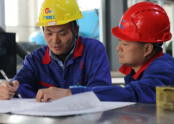
To further ensure the quality of the operation-side support roller bearing seat, GW Precision performs dimensional inspection in addition to routine size checks.
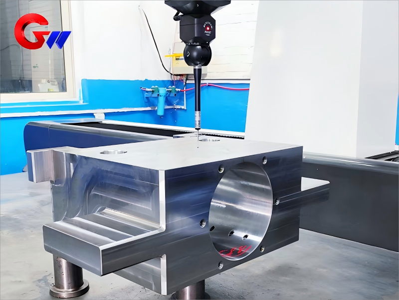
Bearings and other precision-related features can be inspected using a coordinate measuring machine, with measurement accuracy reaching the 2-micron level.
The inspection process provides a controlled basis for verifying dimensional accuracy, form and position tolerances, bearing-hole geometry, mounting interfaces, and other critical features.
Inspection data can be recorded according to applicable production and contractual requirements.
The quality-control process covers material verification, machining-process control, dimensional inspection, precision measurement, cleaning, and final release.
For components used in a hot rolling mill, this process-oriented approach helps maintain consistent manufacturing quality and provides traceable inspection information for critical functional dimensions.
Packaging
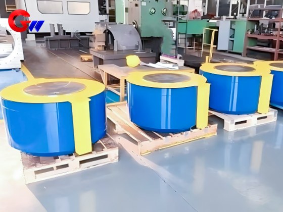
GW Precision maintains dedicated packaging procedures for bearing seat products.
The packaging process is designed to protect the component from loss, impact, contamination, and damage during storage, transportation, and delivery.
Before packing, the product surface is cleaned and checked to confirm the required cleanliness. Appropriate protective measures are applied to precision-machined surfaces, bearing interfaces, mounting surfaces, and other areas requiring protection during transportation.
Controlled packaging helps preserve the dimensional and surface condition established during machining and final inspection, allowing the support roller bearing seat to reach the customer in a suitable condition for subsequent assembly.
Bearing Coordination and Lubrication
Bearing Type Adaptation
The operation-side support roller bearing seat can be configured for four-row tapered roller bearings, such as SKF TQO series bearings, or oil-film bearing systems, such as MORGOIL, according to the mill design and operating requirements.
The bearing arrangement is selected according to rolling load, roll dimensions, operating speed, lubrication configuration, and the structural design of the mill.
Matching Tolerances
The specified bearing fits are:
Bearing outer ring and seat hole: Transitional fit, H7/k6
Bearing inner ring and roller neck: Interference fit, H7/S6
These fits establish a controlled relationship between the bearing components and their corresponding mounting interfaces.
Accurate fit selection is important for the bearing seat because excessive clearance or interference can affect bearing positioning, load distribution, installation quality, and long-term operating stability.
Lubrication Requirements
For thin-oil lubrication, the specified lubricant is:
ISO VG 220–320 extreme-pressure gear oil
For oil-air lubrication:
Pressure: 0.2–0.5 MPa
Flow rate: 5–10 L/min
The lubrication configuration should be selected according to bearing type, rolling speed, load, temperature, and the lubrication system of the mill.
Proper lubrication helps control friction and heat generation and supports stable bearing operation during continuous rolling. For a hot rolling mill, an appropriate lubrication system is particularly important because the bearing assembly may operate under high loads and elevated thermal conditions.
Application in Hot Rolling Mill Systems
The operation-side support roller bearing seat is intended for support-roll assemblies used in hot rolling mill systems.
It provides the mechanical interface between the bearing arrangement and the mill structure while supporting accurate positioning of the support roll.
Depending on the equipment configuration, the bearing seat can be engineered with different material grades, bearing arrangements, machining requirements, dimensional tolerances, and lubrication solutions.
This flexibility allows the component to be adapted to conventional, high-load, and high-speed rolling conditions.
By combining suitable structural materials, controlled machining, precision inspection, defined bearing fits, and appropriate lubrication, GW Precision provides support roller bearing seat solutions designed for reliable operation in demanding industrial rolling environments.
Bearing coordination and lubrication of operate side roller bearing seat
Bearing type adaptation:
Four row tapered roller bearings (such as SKF TQO series) or oil film bearings (MORGOIL)
Matching tolerance:
Bearing outer ring and seat hole: transitional fit (H7/k6)
Bearing inner ring and roller neck: interference fit (H7/S6)
Lubrication requirements:
Thin oil lubrication: ISO VG 220~320 extreme pressure gear oil
Oil air lubrication: pressure 0.2~0.5MPa, flow rate 5~10L/min